Menu

Oxford Thermofluids Institute | Facilities - Other Facilities

Other Facilities

Annular Sector Heat Transfer Facility
Large Scale Platform Cooling Facility
Cold Driven Shock Tube
Probe Calibration Facilities
Annular Sector HT facility
Sector Facility Working Section
Overall Cooling Effectiveness Measurements

Annular Sector Heat Transfer Facility

The thermal performance of cooling systems for high-pressure nozzle guide vanes (HPNGVs) is typically assessed at engine conditions using a thermal-paint-test engine as part of the engine certification process. Such tests are generally restricted to final qualification of cooling systems before production. Promising cooling systems with some element of design risk (lower TRL) would not normally be tested in engine products. This extends the time required for new technology to enter service engines. 

The continuing maturation of metal laser-sintering technology (DMLS) and the ability to reproduce thermal-paint test conditions in the laboratory environment presents two opportunities: firstly supplementing thermal paint test engines to de-risk the engine design process with additional tests during the engine development programme; and secondly the chance to test promising designs of lower TRL to accelerate the rate at which technology is transitioned from research into engine products. 


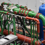
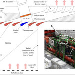
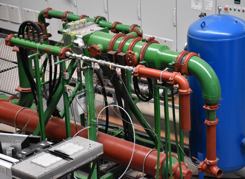
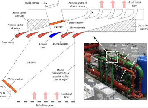
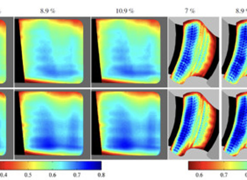
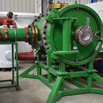
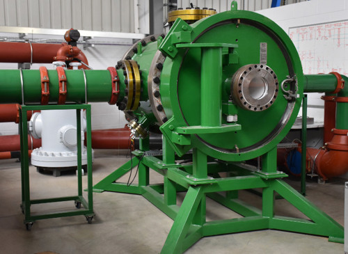
The Annular Sector Heat Transfer Facility (Sector Facility) at the University of Oxford, operates using engine-realistic geometry, and at correct M, Re and coolant-to-mainstream pressure ratio. We have demonstrated that it is possible to assess the overall thermal performance of laser-sintered and conventionally cast parts, and to scale between the results. Using techniques developed in the facility the first openly reported thermal assessment of an entire laser-sintered vane at sufficiently engine-realistic conditions to support the use of laser-sintered components as a developmental tool within the design optimisation process has been presented. 


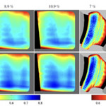
A number of promising next-generation cooling systems have previously been investigated and developed in the Sector Facility, e.g., dendritic cooling systems [1] and reverse-pass cooling systems based on the ideas in [2]. The facility has also been used to conduct comprehensive parametric studies, of, for example, coolant mass flow rate. 

[1] Luque, S., Batstone, J., Gillespie, D.R.H., Povey, T., and Romero, E., 2014, “Full Thermal Experimental Assessment of a Dendritic Turbine Vane Cooling Scheme,” 136. 

[2] Kirollos, B., and Povey, T., 2014, “Reverse-Pass Cooling Systems for Improved Performance,” Journal of Turbomachinery, 136. 

[3] Kirollos, B., Povey, T., 2017, “Method for Accurately Evaluating Flow Capacity of Individual Film-Cooling Rows of Engine Components” ASME Journal of Turbomachinery, Vol. 139, 111004, doi: 10.1115/1.4037028. 

The group also performs theoretical work on cooling system optimisation ([4], [5]) 

[4] Kirollos, B., Povey, T., 2016, “Cooling Optimization Theory—Part I: Optimum Wall Temperature, Coolant Exit Temperature, and the Effect of Wall/Film Properties on Performance,” ASME. J. Turbomach., 138(8):081002-081002-12. doi:10.1115/1.4032612. 

[5] Kirollos, B., Povey, T., 2016, “Cooling Optimization Theory—Part II: Optimum Internal Heat Transfer Coefficient Distribution,” ASME. J. Turbomach., 138(8):081003-081003-15. doi:10.1115/1.4032613. 

Earlier work on the development of techniques in the facility can be found here ([6], [7]): 

[6] Luque, S., and Povey, T., 2011, “A Novel Technique for Assessing Turbine Cooling System Performance,” Journal of Turbomachinery, 133. 

[7] Luque, S., Aubry, J., and Povey, T., 2009, “A New Engine-Parts Annular Sector Cascade to Prove NGV Cooling Systems,” 8th European Conference on Turbomachinery, Fluid Dynamics and Thermodynamics, Verlag der Technischen Universtat Graz, Graz, Austrai, March 23-27, pp.865-878. 

Large Scale Platform Cooling Facility

High-pressure (HP) nozzle guide vane (NGV) endwalls are often characterized by highly three-dimensional (3D) flows. The flow structure depends on the incoming boundary layer state (inlet total pressure profile) and the (static) pressure gradients within the vane passage. In many engine applications, this can lead to strong secondary flows. The prediction and design of optimized endwall film cooling systems is therefore challenging and is a topic of current research interest. Detailed experimental investigations of the film effectiveness distribution on engine-realistic endwalls geometry can be performed at the Large-Scale Platform Cooling Facility by means of infrared (IR) thermography. Adiabatic film effectiveness distributions can be measured using IR cameras, and tests can be performed across a wide range of coolant-to-mainstream momentum-flux and mass flow ratios (MFRs). 


The facility is a large-scale, low-speed linear cascade with seven vanes. The facility was designed during the earlier work of Thomas [1]. The aerodynamic profile is based on a modern engine geometry. The vane and endwall geometries include engine realistic features such as the combustor-turbine gap, hub and casing annulus line profiles, and vane fillets. A drawing of the test facility is shown in Figure 1. The facility includes a rich-burn combustor simulator with scaled dilution holes to set high turbulence intensity with representative length scales upstream of the NGV cascade. Removable cassettes at the hub and case allow back-to- back tests of different endwall film cooling designs. An example of the test section is given in Figure 2. The removable cassettes, NGV endwalls, and combustor simulator are manufactured from Rohacell, a structural material with very low thermal conductivity, to allow film effectiveness measurements to be performed using infrared thermography with minimal conduction error. The mainstream inlet flow is heated with an upstream heater mesh. Hub and casing endwall coolant mass flow rates are measured using critical-flow Venturi nozzles. The mainstream and coolant flow temperatures are measured with thermocouples and surface temperature measurements are obtained with foil thermocouples on the endwall surfaces. 


Complex interactions between coolant film and vane secondary flows were presented and discussed in [2]. A particular feature of interest is the suppression of secondary flows (and associated improved adiabatic film effectiveness) beyond a critical momentum flux ratio. Jet liftoff effects are also observed and discussed in the context of sensitivity to local momentum flux ratio (an example of the results is given in Figure 3). Full coverage experimental results are also compared to 3D, steady-state computational fluid dynamics (CFD) simulations. The work in [2] provides insights into the effects of momentum flux ratio in establishing similarity between cascade conditions and engine conditions and gives design guidelines for engine designers in relation to minimum endwall cooling momentum flux requirements to suppress endwall secondary flows. 

[1] Thomas, M., 2014, “Optimization of Film-Cooling in Axial Turbines,” PhD thesis, University of Oxford, Oxford, UK. 

[2] Ornano, F., Povey, T., 2017, “Experimental and Computational Study of the Effect of Momentum-Flux Ratio on High-Pressure Nozzle Guide Vane Endwall Cooling Systems,” J. Turbomach, 139(12):121002-121002-14. 

Cold Driven Shock Tube

Cold Driven Shock Tube

The Cold Driven Shock Tube (CDST) is a double diaphragm, reflected shock tube facility, designed to provide controlled temperatures and pressures up to 1500 K and 150 bar. 


The facility will be used to support fuel spray and auto-ignition research and was funded under the Ultra-Efficient Engines and Fuels project – http://www.eng.ox.ac.uk/engines/research/ultra-efficient-engines-and-fuels. 

Probe Calibration Facilities

Probe Calibration Facilities

The institute also has a number of Probe calibration facilities. These include a new high Reynolds free jet rig and the recirculating low 9 by 3 supersonic tunnel from the National Physical Laboratory (NPL) for transonic flows. The facilities permit the accurate calibration of aerodynamic probes that are used to obtain accurate measurements across experiments at the OTI.