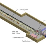
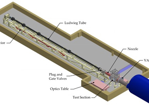
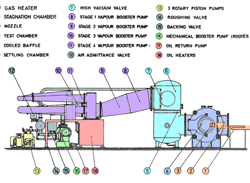
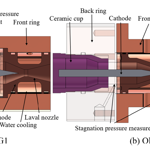
The test gas may be any inert gas and total temperatures up to ~550 K are currently possible, though there are plans to extend this to >1000 K. Acceleration of the test gas from the stagnation chamber is by way of a contoured Mach 6 nozzle, although conical nozzles and orifice plates have been used in the past to achieve free-molecular flow conditions [1, 2]. The current Mach 6 nozzle has an exit diameter of 108 mm and produces a core flow region of 40 mm diameter, depending on the test condition. Other Mach number nozzles may be developed in the range 4 to 12.
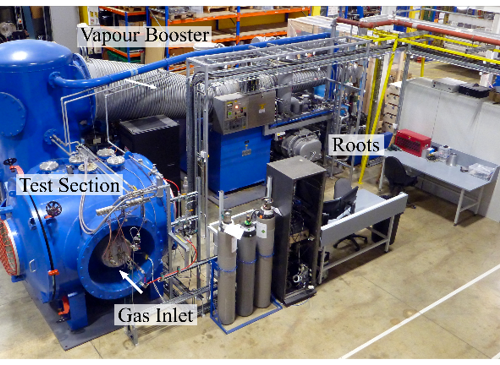
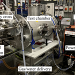
The test section consists of a large cylindrical vessel approximately 1540mm in diameter and 1500mm length with the axis perpendicular to the nozzle axis. Access to the test section may be from either side through full-size dished doors allowing for the installation of experimental kit.
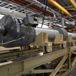
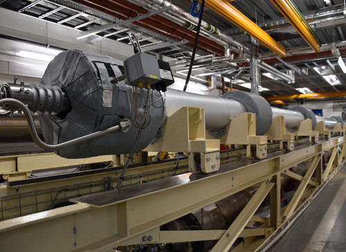
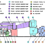
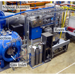
The pumping system at the core of the facility is one of approximately four identical systems produced by Edwards Vacuum at the time of manufacture (early 1960s). It consists of an Edwards 100B4 ejector vapour booster pump backed by an 1R80 Roots-style mechanical booster pump and three HISC3000 rotary piston pumps. As a whole, the system is capable of pumping 22 000 l/s at back pressures up to ~2 Pa. With no gas admittance, the system is capable of achieving an ultimate pressure of ~0.01 Pa. The facility has been refurbished and recommissioned over the period 2014 – 2018, further details of which may be found in Donaldson et al. [3].
The Oxford Low Density Tunnel is suitable for experimentally investigating aero-thermal phenomena at high altitudes (approx. 70 – 90 km) such as control jets, multi-body interactions including shock-shock and shock-boundary layer interactions. It is well suited for characterising the heat transfer to satellites or debris during re-entry.
Experimental techniques currently employed include heat transfer measurements using liquid crystals, infrared thermography or thin-film heat transfer gauges and aerodynamic force measurements using a load-cell. A multi-axis traverse system is employed and an existing 3-component magnectic suspension balance system is to be recommissioned to enable precise force measurement and sting-free model attitude control.
Previously the LDT has been used to investigate:
- the heat transfer distribution on satellite anologue geometries (flat faced cylinders, hemisphere cylinders, etc)
- the effect of wall-to-temperature ratio on the drag of spheres and cones across the range of contimuum to free-molecular flow
- the variation in lift and drag of cones at angle-of-attack with Knudsen number
- wake flows behind vehicle analogue geometries
- comparisons between DSMC simulations and experimental drag measurements for cones and Aerobrake geometries
References
[1] Haslam-Jones, T. F., “Measurements of the Drag of Slender Cones in Hypersonic Flow at Low Reynolds Numbers using a Magnetic Suspension and Balance,” DPhil thesis, University of Oxford, Department of Engineering Science, Oxford, UK, 1977. Also Dept. of Eng. Sci. Report 1235/78 (1978).
[2] Hadjimichalis, M., “A Study of Sphere Drag in the Transition from Continuum to Free Molecular Flow,” DPhil thesis, University of Oxford, Department of Engineering Science, Oxford, UK, Oct. 1973. Also Dept. of Eng. Sci. Report 1073/73 (1973).
[3] Donaldson, N., Doherty, L. J., Ivison, W., Wilson, C. F., McGilvray, M., and Ireland, P. T., “Refurbishment and Characterisation of the Oxford Low Density Hypersonic Wind Tunnel,” International Conference on Flight Vehicles Aerothermodynamics and Re-entry Mission & Engineering (FAR), ESA, Manopoli, Italy, 2019.