Low Speed Heat Transfer Facilities

Low Speed Heat Transfer Facilities


Wall Block Cooling Rig
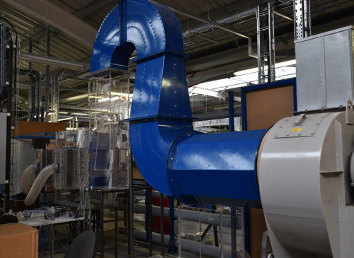
The Wall Block Cooling facility is low-speed recirculating wind tunnel capable to producing core flow temperatures of 200 °C The facility was principally designed to investigate the cooling performance achieved from novel turbine cooling geometries that in turn result in increased efficiency of aero-engines. These cooling geometries are termed double-wall effusion and transpiration systems and represent the pinnacle of turbine cooling. The setup is particularly novel in the steady-state use of a heater mesh to provide uniform heated flow, and also in the use of high-performance insulation lining the inside of the tunnel to reduce the time taken for the facility to reach a steady condition at which point testing of the geometries can commence.
The experiments use infrared cameras to obtain both film- and metal-effectiveness measures for ×10 scale cooling geometries, matching important dimensionless parameters to engine condition in the process; namely Reynolds and Nusselt numbers. Further details on the facility can be seen in the following publication: https://doi.org/10.1115/1.4047384


Combustor Turbine Interaction Facility
The Oxford Combustor-Turbine Interaction (CTI) rig employs an upstream combustor simulator to produce engine realistic approach flow conditions for a large scale, two-passage NGV cascade test section.
The combustor simulator features endwall film cooling, and opposed dilution ports to generate large scale, high intensity turbulence similar to that experienced in a modern civil turbofan engine. The cascade geometry is a linear extrusion of a modern engine NGV midspan cross section. The leading edge of the central vane is film-cooled. It is an easily removed, separate piece, which permits collection of both external surface temperature (via infrared measurements) and pressure (internal and external, via pressure tappings) data in high resolution and on multiple, rapidly prototyped leading edge geometries.
With the mainstream gas path heated electrically by a heater mesh, high density foam leading edges permit film effectiveness to be measured at steady-state. 3D-printed polymer leading edges feature internal pressure tappings. Tailboards downstream of the cascade are adjusted to simulate a periodic test section pressure distribution on the central vane.

