Menu

Oxford Thermofluids Institute | Facilities - Cascade Facilities

Cascade Facilities

High Speed Linear Cascade
High Speed PSP Rig
Transonic Rotor Cooling Facility
Supersonic Cascade Facility
High Speed Linear Cascade Schematic
High Speed Linear Cascade end view
High Speed Linear Cascade
High Speed Linear Cascade CAD
High Speed Linear Cascade Schematic
Schematic
3D tour
High Speed Linear Cascade end view
High Speed Linear Cascade
High Speed Linear Cascade, internal view
High Speed Linear Cascade CAD
CAD drawing of High Speed Linear Cascade
High Speed Linear Cascade CAD
Labelled schematic

High Speed Linear Cascade

The High Speed Linear Cascade (HSLC) is a blowdown wind tunnel with engine realistic Mach and Reynolds numbers, designed to evaluate the heat transfer characteristics of high-pressure turbine blade tips. The test section consists of five blades, with the middle three having swappable tips and being equipped with a controllable coolant distribution system, employed to study possible cooling scheme optimisations.

Experimental programs typically analyse combinations of tip clearances and coolant mass flow rates to characterise the performance envelope of novel tip cooling technologies. Binary pressure sensitive paint is used to measure the adiabatic film cooling effectiveness over the tip surface, which is supplemented by heat transfer coefficient measurements obtained via infrared thermography. Aerodynamic performance is measured via a 4-hole probe at cascade exit and is combined with inlet traverse data to evaluate the impact of tip designs on stage performance.

High Speed PSP Rig

The High Speed PSP rig was designed and commissioned to obtain high subsonic flow around a spanwise uniform aerofoil. It is a blowdown test facility with a scaled single blade passage modelled out of Perspex for unhindered visibility of the aerofoil.

Pressure sensitive paint (PSP) is an optical tool that detects Oxygen concentration over a PSP coated surface. This non-intrusive measurement technique is used to study the effect of film cooling over an airfoil by including a foreign gas, compressed Nitrogen in this case, in the coolant feed. An in-situ calibration method has been developed for the PSP. The data from experiments is gathered using monochromatic cameras with a good resolution and high SNR for flow feature resolution, while a low frame rate is sufficient to log the steady state phenomena. Each film cooling design is examined over a range of coolant mass flow rates (set using accurate mass flow controllers), under almost identical mainstream flow conditions.

The facility also has provision to perform heated-flow experiments through a heater mesh connected to the drake power supply.

3D CAD representation of working section in the transonic rotor cooling facility.
3D CAD of visible rotor platform area for IR metal effectiveness measurements and internal cooling feed representative of engine geometry

Transonic Rotor Cooling Facility

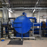
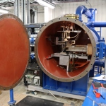
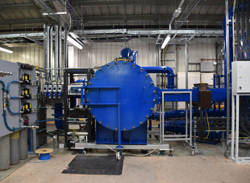
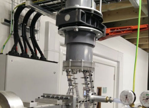
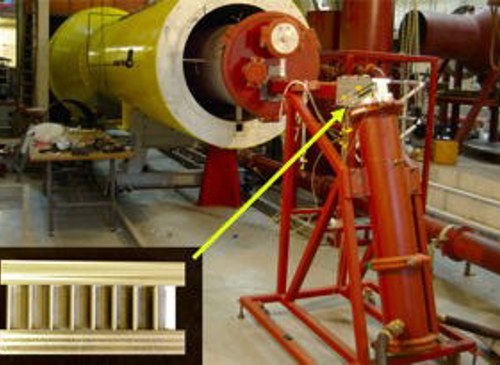
The Transonic Rotor Cooling facility at the University of Oxford is a new high-pressure linear cascade designed for low technology-readiness level research of rotor platform cooling. It will be used for aerothermal research into flow interactions between seal leakages across the platform, to develop and assess novel cooling systems, and computational fluid dynamics validation.

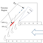
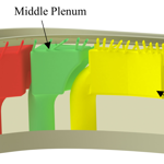
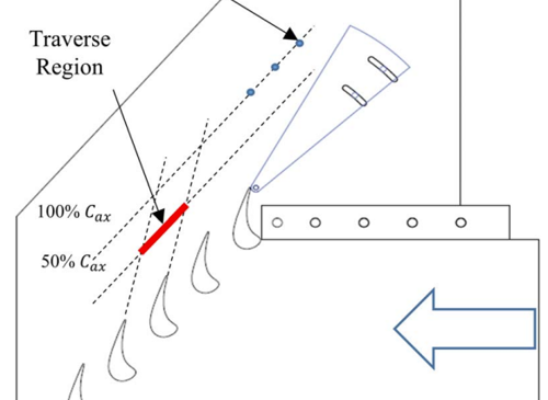
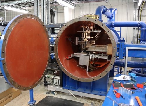
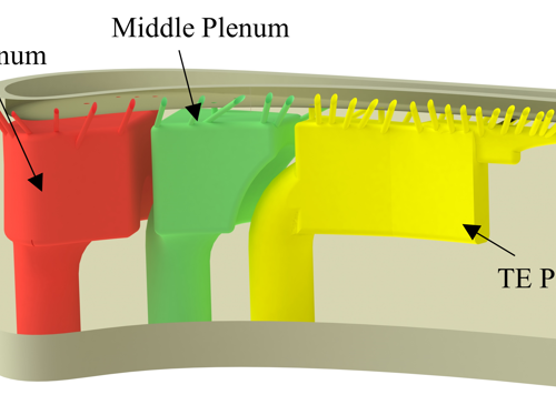
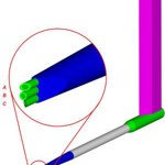
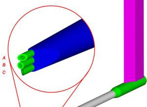
The test section contains five rotor blade passages formed by linearised versions of engine components and bounded by contoured endwalls. Test components are complete scaled-up blades, which include fir tree roots, housed in a modular cassette representative of engine disk and hub seal geometry. This novel arrangement allows for all seal leakage flows and their aerothermal impact on platform cooling to be assessed. The coolant supply to the front hub seal, shank pocket and blade, and rear seal can be varied independently. The flexibility of coolant supply, and modularity of the test section, allows for varied cooling systems to be implemented in the blade platforms. Limited geometric changes, such as the introduction of swirl fins, can also be made to the front and rear hub seals to, for example, model the effect of rotation-induced swirl on the cooling performance of leakage flows.

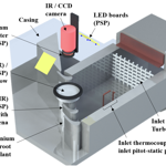
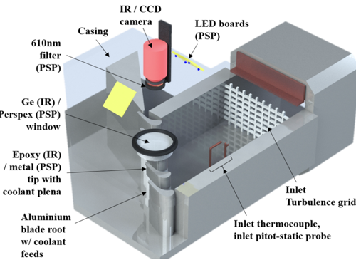
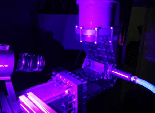
The facility operates at scaled engine conditions with matched Mach number, Reynolds number, coolant-to-mainstream pressure ratios, and inlet turbulence intensity. Overall cooling effectiveness measurements of two complete blade platforms can be obtained with a high level of precision via infrared thermography. Measurement techniques developed previously in the University of Oxford Sector facility will be employed so that thermal assessments can be made using laser sintered test components. This allows for a rapid turnaround of components and significantly reduces the time and costs of introducing and modifying platform cooling systems. Aerodynamic measurements are also possible to allow for aerodynamic performance effects of cooling to be examined.

Supersonic Cascade Facility

Supersonic Cascade Facility

The supersonic cascade facility is a new two-dimensional mini-cascade blow-down tunnel, with 8 vane passages of only 15 mm pitch and 40 mm span. It has been developed for testing gas turbine nozzle guide vane profiles at transonic exit Mach numbers and realistic Reynolds numbers with a quick turnaround and high accuracy.

The small size of the cascade has many advantages. Vane profiles can be tested at adjustable engine representative Reynolds numbers at room temperature with exit static pressures above atmospheric and Re and Mach number can be independently varied. The mass flow is small and the long (> 3 minutes) run times allow downstream traversing with a 3-hole miniature probe. The inaccuracies inherent in the traditional method of mounting the blades on pegs in the schlieren windows has been eliminated by accurately CNC machining the whole cascade of blades integral with the tunnel side walls, with re-usable, plug-in Schlieren windows. Cascades of new test blade profiles are quickly machined and tested, with a fast turn-around for comparative studies. A new Schlieren photography system captures multiple flow visualisation images per run directly into a digital SLR camera.

A number of transonic cascade profiles have been investigated, and demonstrate that the tunnel performs well in the subsonic and low supersonic region, but, as the exit Mach number increases, shock wave reflections from the free jet boundary, seen on the schlieren, cause non-periodicity. Interestingly, if the downstream pressure is reduced further to give even higher (but unrealistic) Mach numbers, the cascade becomes axially supersonic and excellent periodicity is restored.

Using this tunnel the flow in supersonic cascades is investigated using downstream traverse measurements (for loss), schlieren photographs for detailed understanding of the shock structures, and CFD simulations of the tunnel flow