Oxford Thermofluids Institute | Research - Research Groups: CFD Group, Unsteady Flows

Unsteady Flows
Unsteady flows in turbomachinery
Nonlinear Unsteady Effect on Time-Averaged Flow (‘Deterministic Stress’)
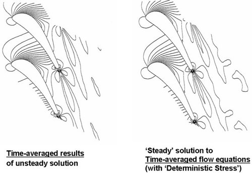
Due to the flow nonlinearity, extra unsteady stress terms will be generated in flow equations when time-averaging. These stress terms are similar to the Reynolds stress terms generated by turbulence but in the cases of interested, they are generated by periodic unsteadiness with a distinctive frequency (e.g. due to trailing edge vortex shedding), hence they are called ‘Deterministic Stress’. Our computational analysis (Ning and He 2001) show that a steady-state solution can be obtained by adding the deterministic stress terms to the unsteady flow equations. Without these stress terms the solution will be naturally unsteady, giving a periodic trailing edge vortex shedding. On the other hand, once these stress terms are added, the solution is stabilized, leading to a steady state field which is in agreement with the time-averaged flow field of the unsteady solution.
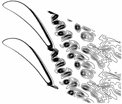
Instantaneous entropy contours (unsteady solution)
Analysis of Deterministic Stress (trailing edge vortex shedding, VKI turbine cascade)
Effects of Circumferential Length Scale and Clocking in Axial-flow Turbomachines
Flow in turbomachinery is inherently unsteady due to the relative motions of adjacent blade rows with circumferential flow non-uniformities. The effects of the unsteady responses are strongly influenced by the circumferential length scales. Examples include:
- Stream turbine under partial admission (He 1997), where at the same partial admission flow rate, the axial propagation of the disturbances is shown to be markedly weakened when the circumferential length scale is halved.
- A periodic unsteady forcing pattern with non equal amplitude and variable inter-blade-phase-angle are induced by the rotor-rotor/stator-stator interactions in high pressure gas turbines (Li and He, 2003).
- High pressure gas turbine under inlet ‘hot streak’ (temperature non-uniformity from combustors), where both the heat load and unsteady forcing on the turine rotor blades show strong dependency on the length scale/hot stream counts (He, Menshikova and Hall, 2007).
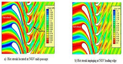
Entropy contours for two clocking positions of Hot streaks at inlet to a high pressure turbine stage
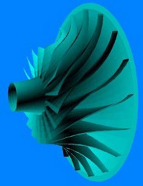
Bladerow Interaction in Radial Flow Turbomachinery
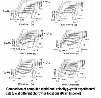
The capability in computing radial turbomachinery components, in particular, the interaction between rotor impeller and stator diffuser has been developed.
The validations were firstly carried out for the Krain centrifugal compressor giving good agreement with the experimental data, followed by a study of the diffuser stall characteristics (Sato and He, 2000). For a vanes diffuser, its interaction with the impeller was analysed (Sato and He, 2000).
In order to analyse unsteady flow at very low speed, an incompressible unsteady flow solver was developed combining the techniques of artificial compressibility for preconditioning and the dual time stepping (He and Sato, 2001). The method had been applied to analysis of hydraulic turbine performance (Sato and He, 2001).
Blade-Tower Interaction in Wind Turbines (HAWT)
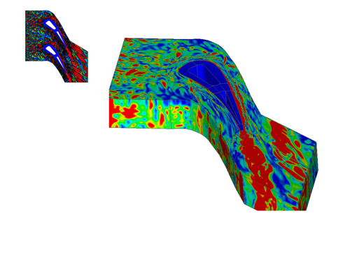
Wind turbine blades are subject to various unsteady flow disturbances which affect both ‘mean’ (time-averaged) work output and system mechanical integrity. Even at a uniform upstream flow condition without any ‘wind shear’, blades of a horizontal axis wind turbine may interact with downstream supporting tower. The work is attempted to predict unsteady aerodynamic effects of blade-tower interaction using a time-dependent computational fluid dynamics approach. The flow field is governed by the Reynolds averaged unsteady Navier-Stokes equations, discretized in space using a finite volume scheme and integrated in time using an explicit time-marching scheme. The computational domain consists of multiple structured mesh blocks (Fig.1), with body-fitted meshing for both a stationary tower and a moving blade. The moving mesh around the blade and the stationary mesh around the tower are connected by a sliding interface in conjunction with a 2nd order interpolation technique , which produces continuous information exchanges across the interface, as shown in Fig.2 for instantaneous static pressure contours. A computation for a blade of NACA 63215 profile indicates more than 10% peak-to-peak variation of the circumferential force when the blade passes the tower (period variations of a similar magnitude have been obtained for the axial force). The unsteady behaviour is relevant to time-averaged wind turbine work output performance and blade fatigue life. An issue of interest is how to effectively control/minimise this unsteady loading in WT blade design.
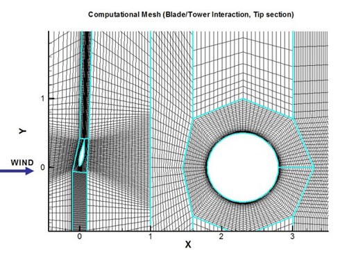
Multi-block moving mesh
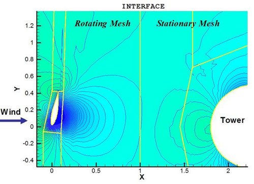
Instantaneous pressure contours
Wells Turbine Stall Control
A variable stator configuration to enhance aero-thermal efficiency and widen operational range of Wells turbines is examined. At a normal upstream/downstream pressure condition, a major cause of low turbine efficiency is the high exit kinetic energy loss due to strong rotor exit swirling flow. The outlet guide vanes (OGV) can then be set according to the rotor swirling flow angle, to effectively reduce the exit kinetic energy loss. On the other hand, when the turbine upstream/downstream pressures exceed the limit causing the rotor to stall, the stator blades can be adaptively set to throttle to offload a large pressure drop to the OGV, while maintaining a constant un-stalled mass flow rate. Furthermore, the variable stator row can be used to control inlet flow angles in the bi-directional Wells turbine set up.
Another simple method of delaying the Wells- turbine stalling is to make use of vortex generators installed near blade hub. The technique was experimentally investigated, showing positive effects (Williams et al, 2005).
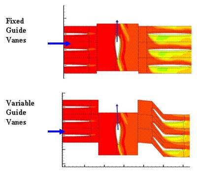
Flow loss (Entropy) contours for Wells turbine
Rotating stall and flow instability
Compressor Rotating Stall Inception
One of the most challenging problems in turbomachinery flow predictions is stall & surge, typically for compression systems (compressors/fans). There have been many research questions attempted by a large number of papers in the last 20 years or so, ranging from the length scales/the driving mechanisms during stall inception (e.g. the short scale ‘spike’ vs the long scale ‘modal wave’), from the role played by rotor tip clearance to what would be an ‘acceptable’ annulus sector as a truncated sector domain of computational analyses, and the ‘best’ turbulence modelling. Our early work was mainly motivated by a qualitative understanding of the possible driving mechanisms by asking ‘what can and should happen when using a CFD model with a lower level fidelity’. This early piece of work and its findings now turn out to be much more relevant, in particular in relation to tip clearance flow, which had been widely regarded to be a key driver in stall inception in the past.
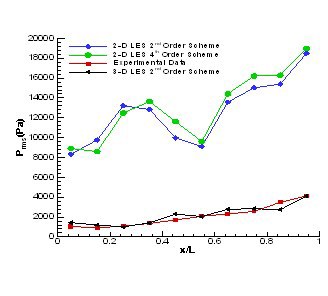
An example of compressor rotating stall inception analysis is given below. The 2D URANS (no tip clearance) is compared to a well-known experimental test data from a rotor rig (3D with tip clearance, of course). These early results and comparisons indicate that tip clearance might not be as a crucial driver for stall inception as might be believed.
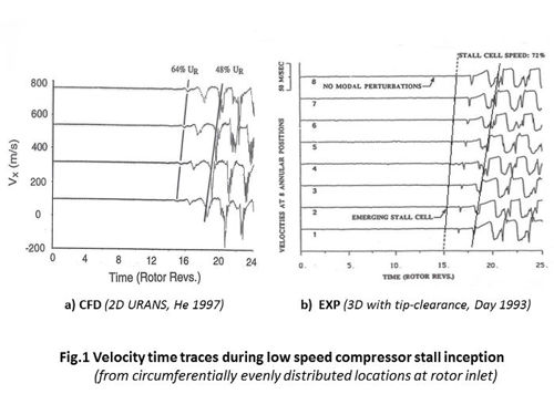
Some further calculations for a rotor row in a 3D multi-passage domain (10 passages, He and Ismael, 1999) had predicted part span 3D stall inception. Again the tip clearance effect was not observed to be very crucial in affecting the inception process. Instead, a major contrast between a subsonic and transonic flows was observed. In a subsonic flow, stall inception was relatively easily detected, whilst in a transonic flow the rotor tended to go to surge without developing into an easily detectable rotating flow pattern first.
Steam Turbine Rotating Instability
Rotating stall and rotating instabilities have been long associated with compressors and fans. It may sound strange that a rotating flow instability can happen in a turbine, but it does!
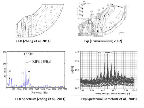
A steam turbine sometimes needs to operate at a very low mass flow condition. The situation becomes more and more common, when flexible operations of steam turbines are increasingly required, e.g. in a combined gas/steam turbine power plant, or in a responsive mode to top up often un-regular renewable generators. Recently some new experimental study has been carried out at University of Stuttgart to reveal that rotating instability happens in a near-tip region of last stage long rotor blades. The CFD prediction at Oxford (Zhang et al, 2010) has produced a similar base flow pattern (below), and rotating instability (thought to be the 1stof the kind CFD prediction of turbine rotating instability). Once again, the results do not indicate that tip clearance is the driving factor.
Large Eddy Simulation of Turbulent Flows
Large Eddy Simulation (LES) of Turbulent Flows
Ingredients of the method development:
- Discretization of The unsteady Navier-Stokes equations using the Space-Time Conservation Element and Solution Element (CE/SE) scheme. The scheme treats the both time and space frames in a unified manner. The numerical results have consistently demonstrated that this 2nd order scheme, possesses very useful properties of high resolution, low dissipation, and non-oscillatory behaviour around shock waves.
- Large Eddy Simulations (LES) is implemented, so that the unsteady NS solver will be able to resolve the transient large scale turbulence structures, whilst only those small scale which can not be resolved at the level of the mesh grid spacing, will be modelled by the Smagorinsky subgrid scale model (SGS)
Large Eddy Simulation of Mixing Layer
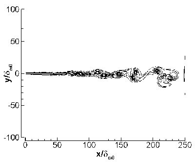
Instantaneous vorcity contours
Normalized Reynolds normal stress
Automobile Cavity Noise
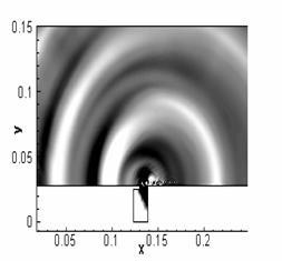
Computation of Screech Tones
The jet is assumed to be supplied by convergent nozzle with a designed Mach number equal to 1. The free stream flow condition is assumed at rest and free stream pressure (P∞) and temperature (T∞) are equal to 105 Pa and 288 K, respectively. Reservoir temperature (Tr) is taken equal to the free stream temperature and an elevated pressure is imposed at the nozzle exit Pe /P∞ = 2.09. Designed nozzle velocity (Ue) is 310 m/s.
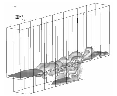
Whole domain and symmetric computations are carried out. For whole domain, computational domain is divided into 64 subdomains and for the symmetric one 32 subdomains are used.
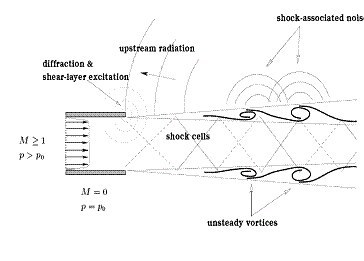
Screech tones generated by under-expanded
Computed Instantaneous density-gradient
Aircraft Weapon Bay Cavity Flow
Three-dimensional large eddy simulation is carried out for subsonic cavity flow. Numerical results are compared with experimental data. The length-to-depth ratio L/D = 5. Flow conditions and geometry details of the cavity can be seen from Table 3. Computational domain is decomposed into 64 subdomains and mesh density is 3.744×10⁶. (250×80×30) cells inside the cavity and (400×130×60) cells above the cavity.
Large Eddy Simulation for Turbine Blades
LES for high pressure turbine blade passages presents a significant challenge chiefly due to the local high Reynolds number. The appeal on the other hand is considerable as the level of inflow turbulence (exit from the combustor) tends to be very high. A further complication is the non-negligible amount of heat transfer, thus leading to the issue of the wall boundary condition for the unsteady energy equation. Recently, some new effort has been made in this area with a particular emphasis on the unsteady fluid-solid conjugate heat transfer interfacing & inflow synthetic turbulence generation (He, 2013).